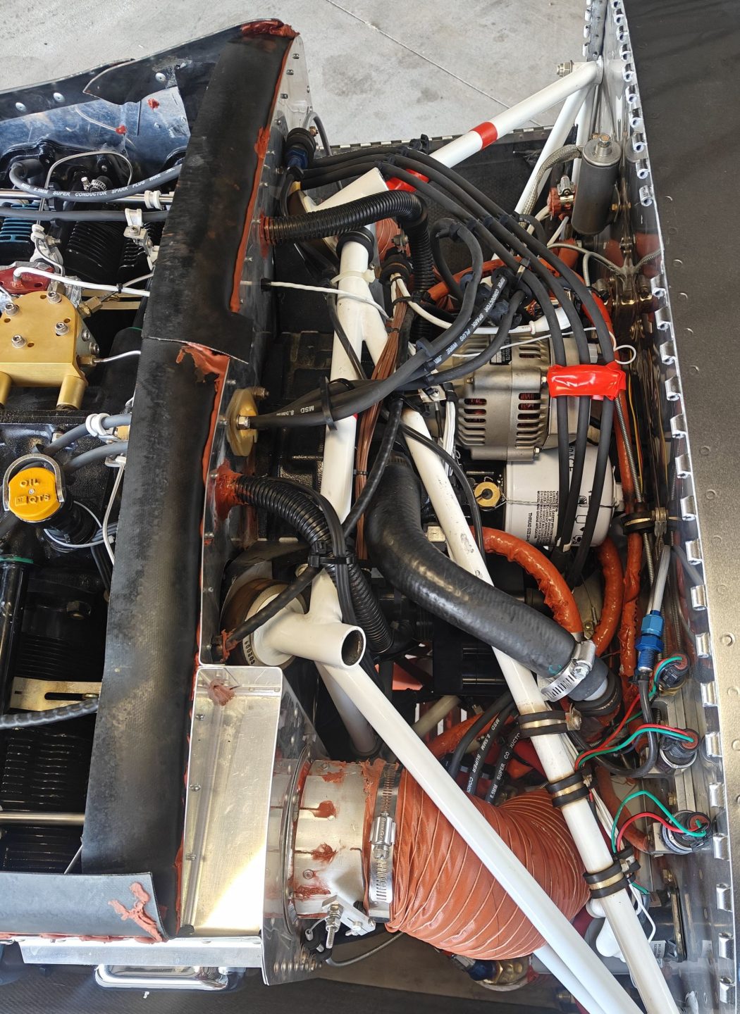
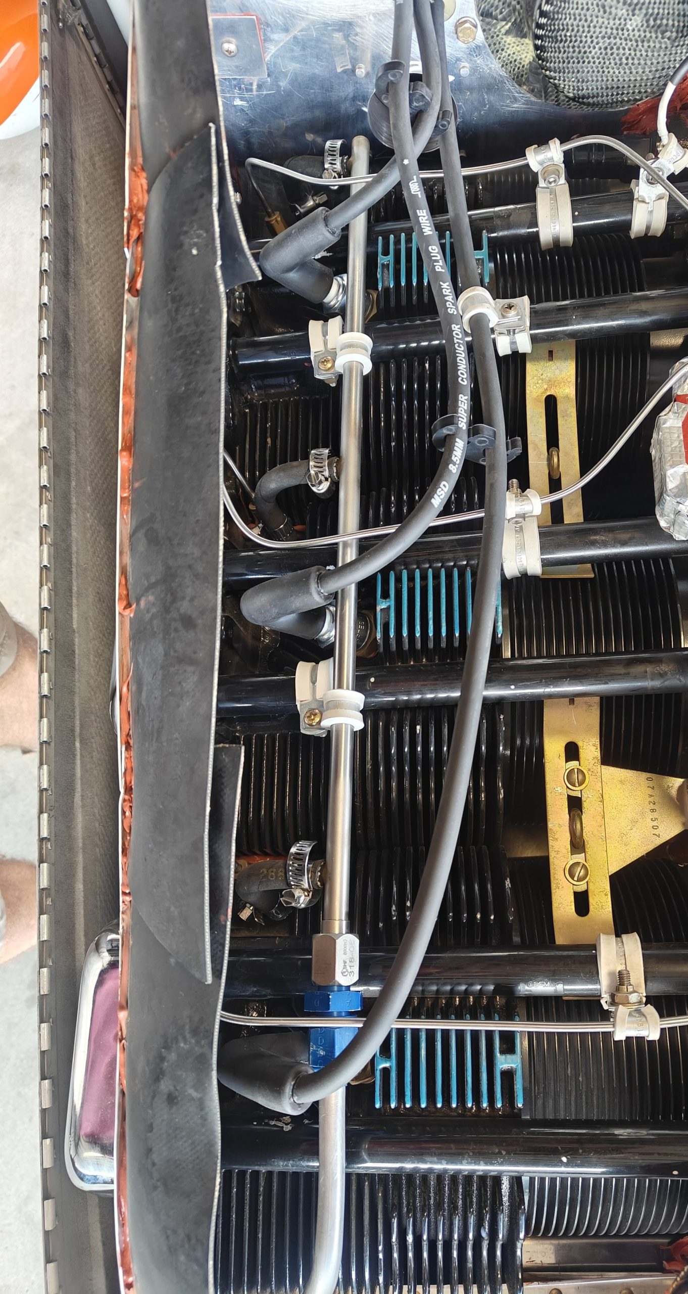
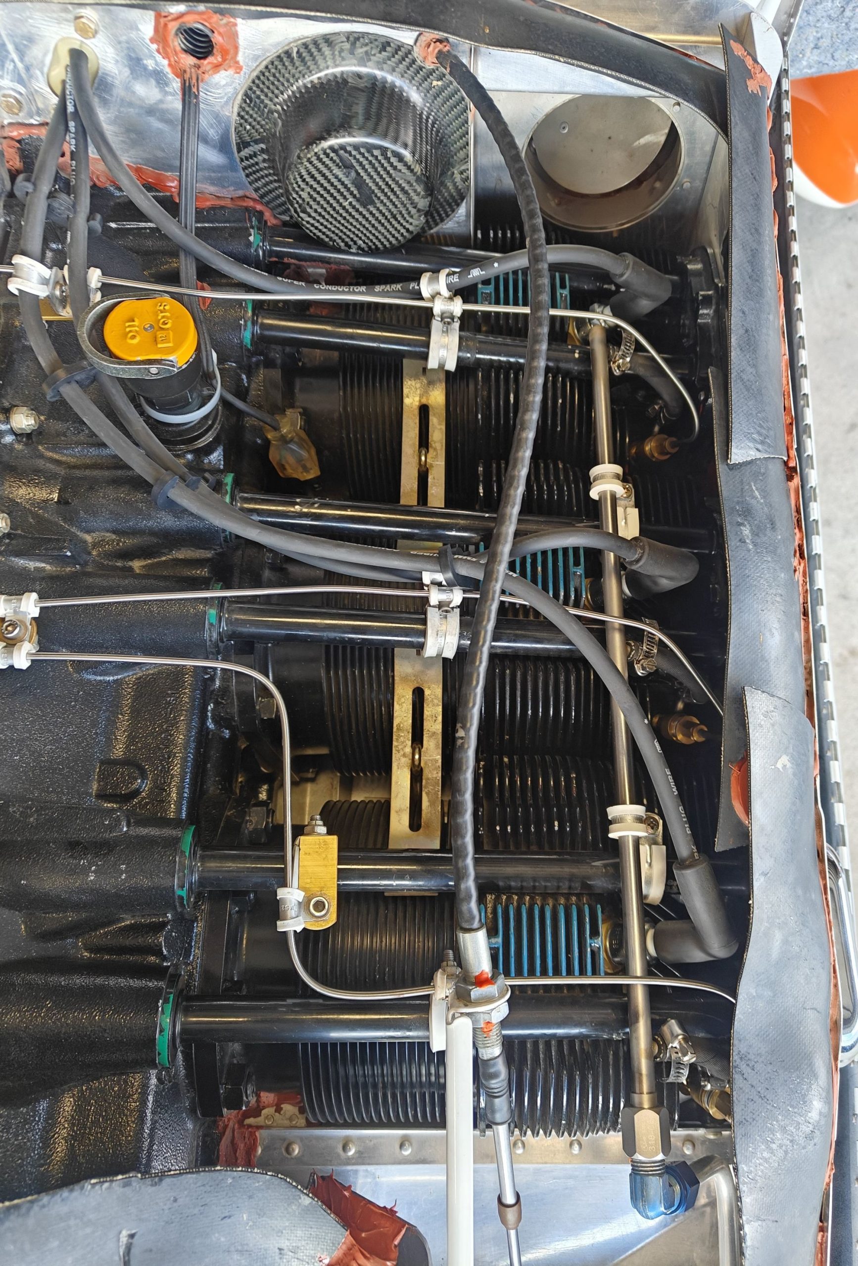
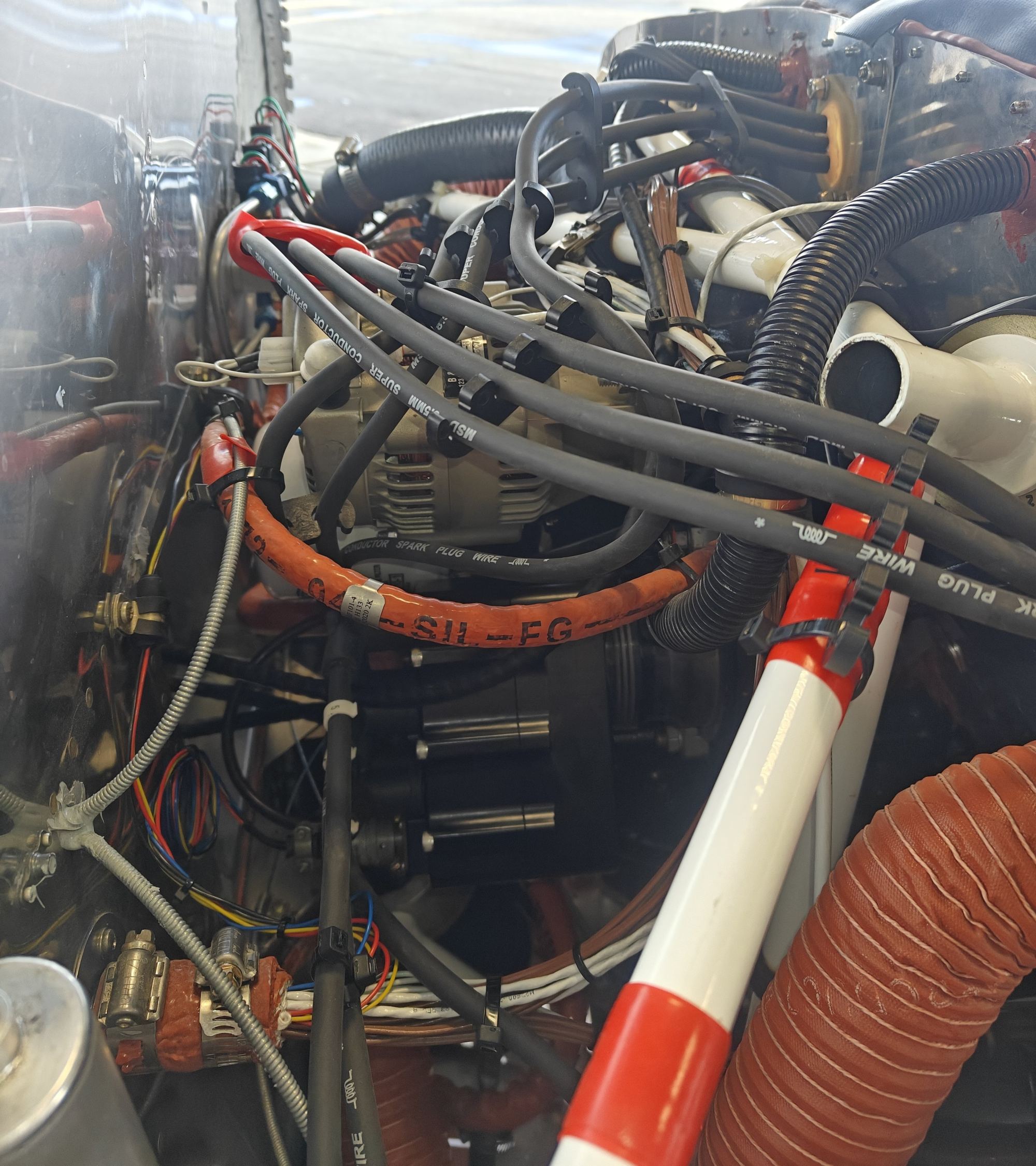
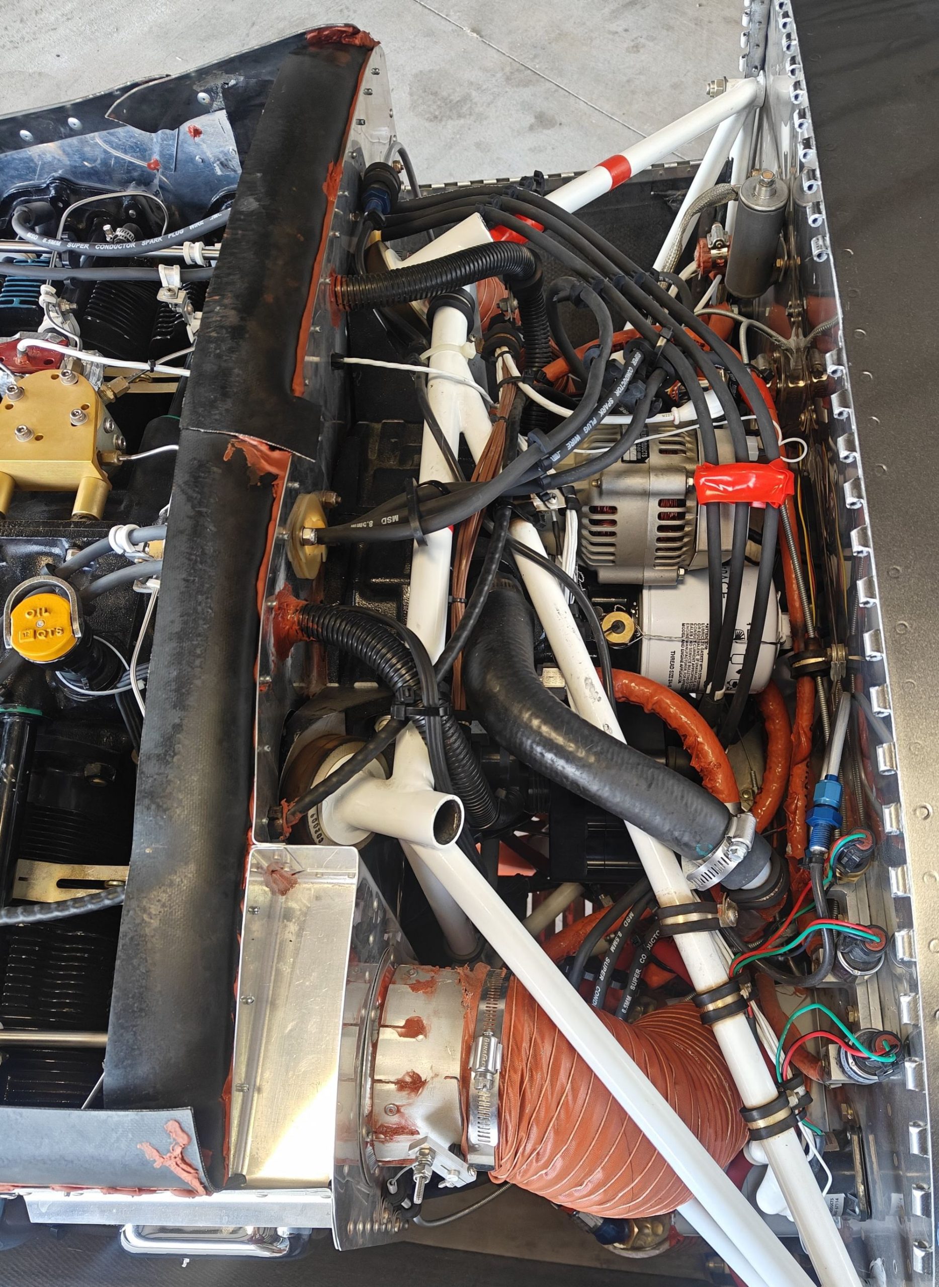
Concerns over a potential mis-fire when running LOP led me to replace the spark plugs and ignition cables plus I was just over 500 hours which is the recommended replacement interval..
Parts ordered:
| Part Number | Manufacturer | Description |
|---|---|---|
| 34023 | MSD | 8.5mm Super Conductor Wire Roll (50 feet) |
| 34614 | MSD | Replacement Spark Plug Wire Terminals (50 pack) |
| N/A | Ton's Performance | Spark Plug Wire Terminal for LS / LT Coil , Long (Qty 25) |
| DL-2048 | Delgada | Wire Crimping Tool for Spark Plug Wires 8-8.5 mm and Terminals |
Note: I reused the boots for both ends
I spent a frustrating few days troubleshooting after ripping out my old ignition cables. Each time I assembled a new cable, I would test its resistance. The initial readings looked great, but after sliding on the protective boot and retesting, the resistance in several cables jumped to 10k ohms instead of the expected 100 to 200 ohms. Despite hours of trial, error, and internet searching, I couldn’t find a solution.
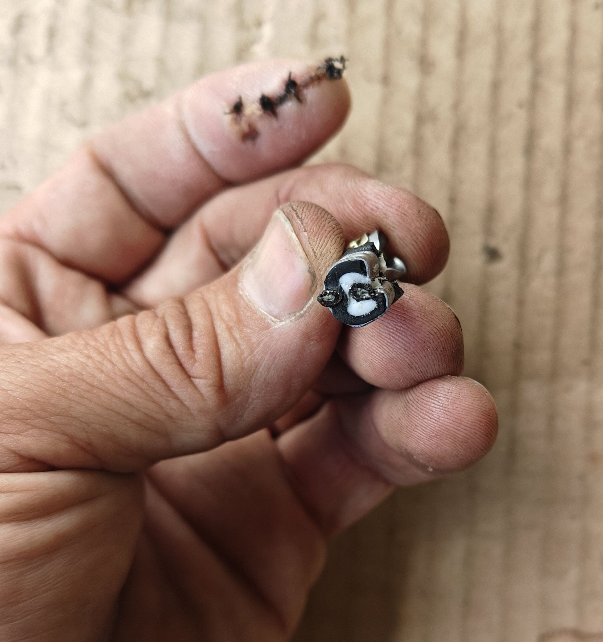
On the morning of the fourth day, I finally found the culprit, the crimping tool was crushing the strain reliefs directly into the cable’s core. To fix this, I changed my process. With the crimp tool, I would only squeeze the first three clicks before releasing it, then used needle-nosed pliers to carefully finish the crimp by hand if necessary. Once I made this switch, I had a 100% success rate with the cables.
Cable Fabrication Steps:
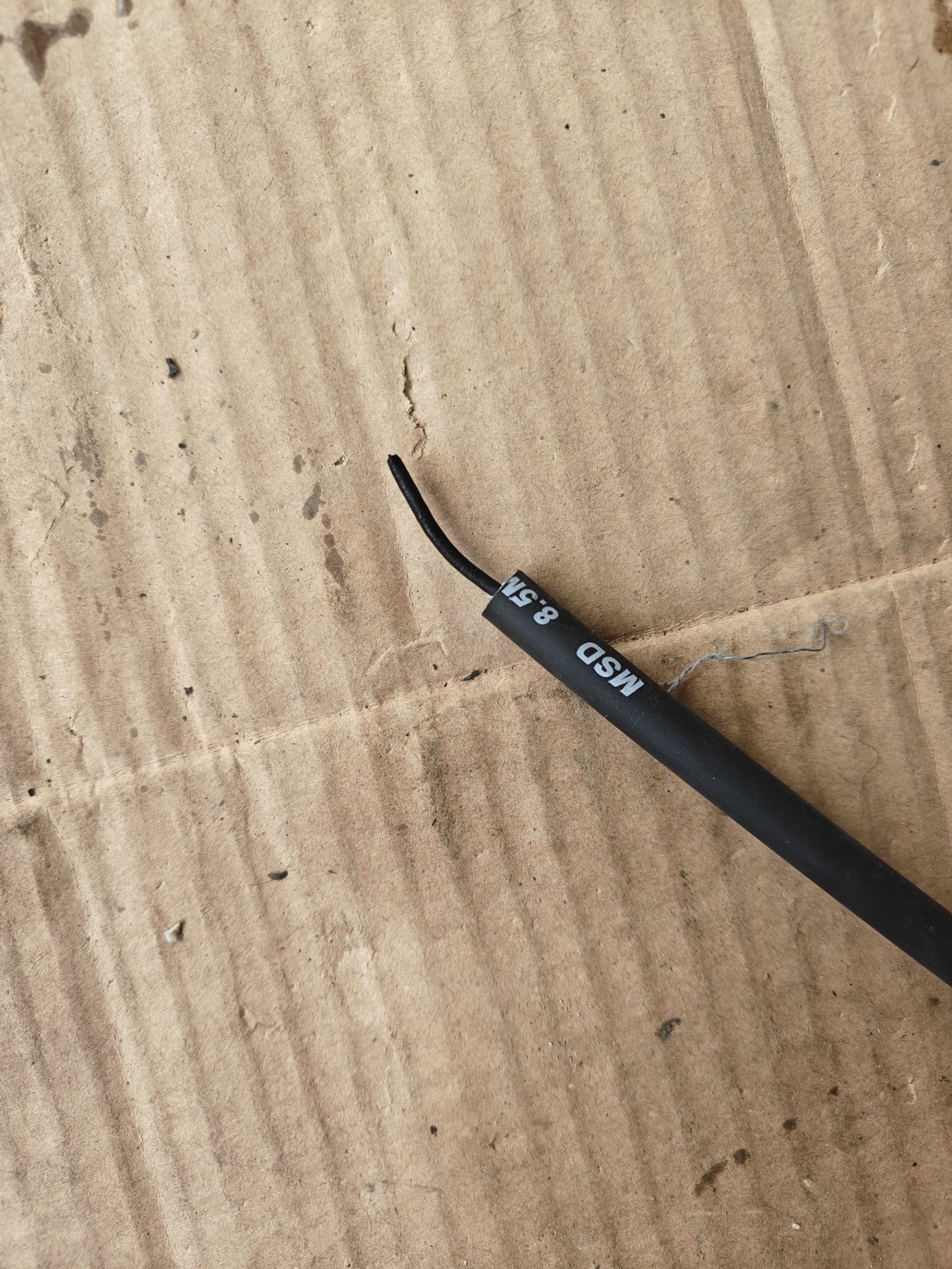
1. Use a razor blade to cut through the black silicon cover and just part way through the white insulation. This required careful work to ensure no damage to the core
2. For the spark plug connector, the crimp tool worked very well to crimp the end of the core to the connector
3. A tug to make sure the wire is tight
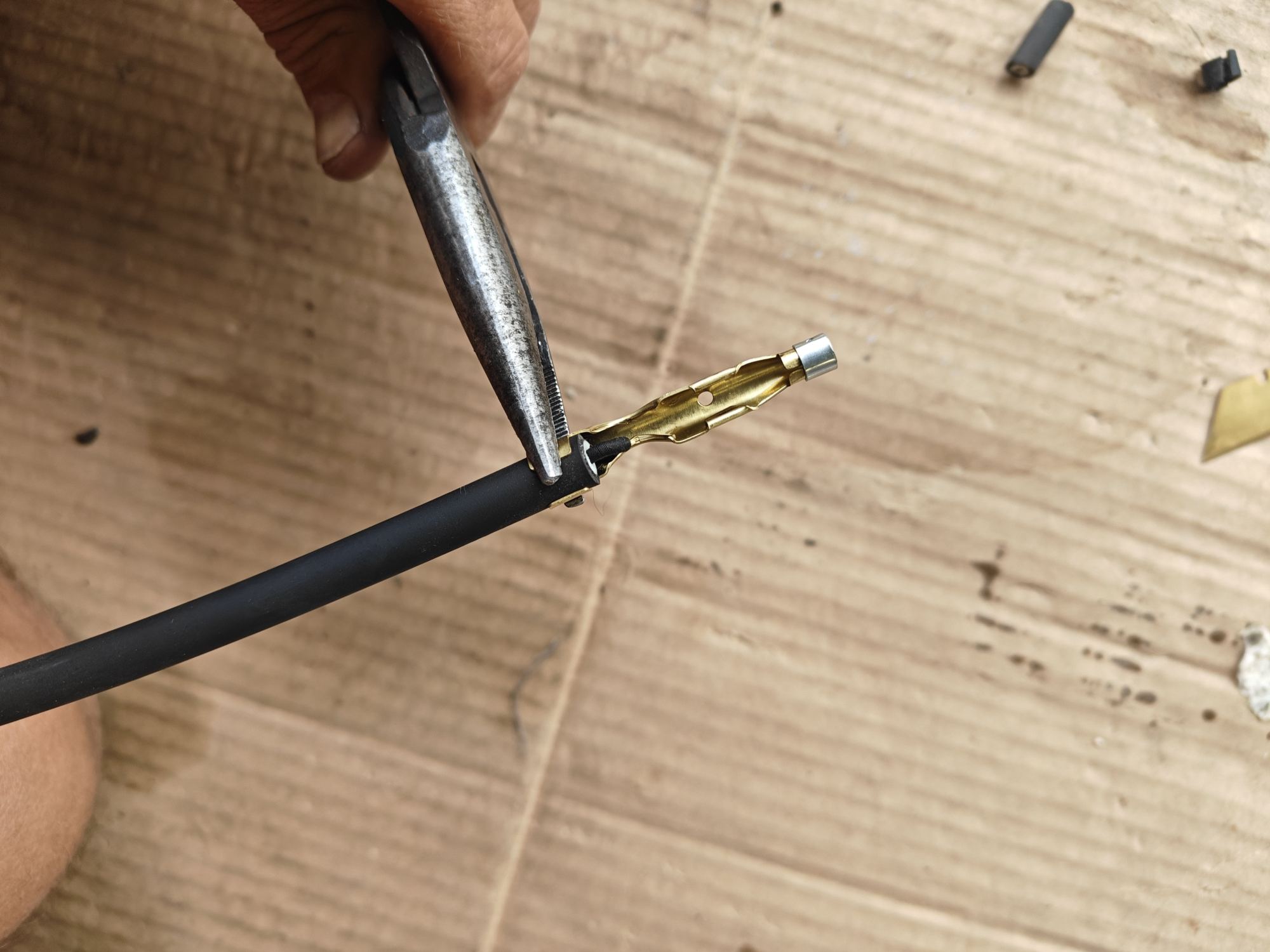
4. Needle nose are used to pre-bend the strain relief, the crimp tool was used to crimp the strain relief (three clicks only), released, and then finished with needle nose pliers
5. A tug to make sure the assembly is tight
6. For the P-mag connector, the core is cut back more so that it can be looped back under the strain relief with a healthy loop
7. Needle nose are used to pre-bend the strain relief, the crimp tool was used to crimp the strain relief (three clicks only), released, and then finished with needle nose pliers
8. A tug to make sure the assembly is tight
9. A multi-meter is used to check the resistance of the assembly
10. The connectors are coated with Molycote electrical insulating compound and slid into the boot on each end
11. A multi-meter is used to re-check the resistance of the assembly
Resistance measurements – Spark plug and Cable testing (after installation):
| # | Location | P/N | Condition | Plug Resistance | Wire Resistance |
|---|---|---|---|---|---|
| 1 | Top | BR7ES | New | 4.16k | 176 |
| 2 | Top | BR7ES | New | 4.17k | 182 |
| 3 | Top | BR7ES | New | 4.34k | 154 |
| 4 | Top | BR7ES | New | 4.09k | 152 |
| 5 | Top | BR7ES | New | 4.25k | 115 |
| 6 | Top | BR7ES | New | 4.20k | 154 |
| 1 | Bottom | BR8EIX 6747 | New | 4.17k | 142 |
| 2 | Bottom | BR8EIX 6747 | New | 4.94k | 144 |
| 3 | Bottom | BR8EIX 6747 | New | 4.75k | 126 |
| 4 | Bottom | BR8EIX 6747 | New | 4.94k | 111 |
| 5 | Bottom | BR8EIX 6747 | New | 4.83k | 101 |
| 6 | Bottom | BR8EIX 6747 | New | 5.25k | 82 |
Final Installation Steps:
1. Check resistance of spark plug
2. Check gap of spark plug
3. Hand tighten spark plug
4. Torque spark plug
5. Apply Molykote to barrel of spark plug
6. Install wire boot (make sure it is aligned with the plug end, slide one while twisting and rocking, once set press boot further onto plug, rock direction of cable exit to ensure the connector is fully seated – it should be rigid)
Vic Syracuse has a good instruction video (starts at 3:50): Link
No Comments