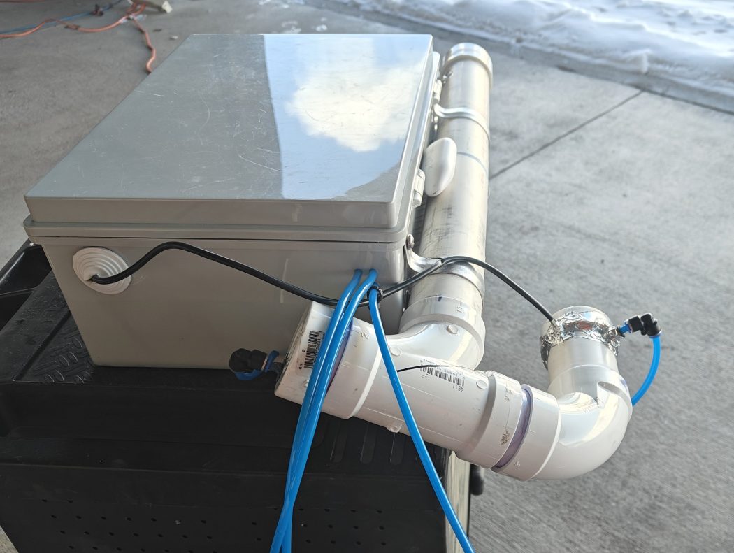
Note: Please see my Version 3.3 post for the current design: Link
Operation:
1. When the humidity reaches 18% and the outputs for two solenoids, a high volume air pump, and the heater are turned ON
2. When the humidity drops back to 10% the heater is turned OFF and the two solenoids and a high volume air pump continue to run for 100 minutes (version 3.1 was 75 minutes) to purge any remaining moisture (once the desiccant tube cools the humidity will drop from 10% to 0.7%)
3. All AC outputs are turned OFF and monitoring continues
* The LED on the PIC18F board flashes one time (for 1/3rd second) for each 10% of humidity followed by one time (for 1/5th second) for each 1% of humidity, so that it is easy to know the current humidity level (5 long flashes with 7 short flashes means the humidity is between 57%).
Interested in how I got to Version 3.3? You can checkout the previous versions:
Version 3.3: Changed the from a solenoid valve to a ball valve for the dry air, removed exhaust tubing, added a second wifi humidity sensor after the dry air solenoid, and modified the “reset humidity” to 19% during the recharge cycle Link
Version 3.2: Change to PVC piping to insert a plug with a small hole on the sensor/dry air side Link
Version 3.1: Change to custom humidity control programming: Link
Version 3.0: Change to custom humidity control PCB: Link
Version 2.0 Change of heating method: Link
Version 1.0: Link
No Comments